This continues the journey of reverse engineering how the Fire is controlled over MIDI and deals with illuminating the buttons and pads.
Lighting the Fire
Having done nothing out of the ordinary for the input side, it’s time to use experience to map the output side and see if we can get anything to light up. The standard way I start is to send Note On events covering all pitches and velocities and see if anything responds and shows some sign of life. Usually sending a Note On to a pad (that triggers a Note On event when pressed) makes that pad illuminate in some way. Here’s the code which does that: it’s simple enough for anybody with a minimal C and MIDI knowledge to understand, with P being the pitch and V the velocity:
for (unsigned Pitch = 0; Pitch < 128; ++Pitch) {
  for (unsigned Vel = 0; Vel < 128; ++Vel) {
    USBH_MIDI_WrEvent(hMIDI, 0x09900000uL + (Pitch << 8) + Vel);
  }
}
What happens on the Fire? Absolutely nothing, no joy whatsoever!
This was a surprise for the buttons but not so much for the pads. That’s because the pads are pretty much true color items, so a single velocity byte whose value is 0 through 127 cannot possibly encode red, green, and blue with enough precision for the colors I’ve seen on the pads.
However, the hope was that the pad would light up anyway, maybe there is a fixed palette with 128 entries that encode a true color—this is the method the standard (non-mini) Launchpad uses to control pad color.
Bummer, no immediate success. Time to move on to figuring out what I can do about it.
Capturing Fire
If the Fire were connected using standard MIDI cables, you could simply sniff the MIDI messages coming over the cable when running an application that communicates with it. However, this is a USB-only device and there is no easy way to tap the connection between the two.
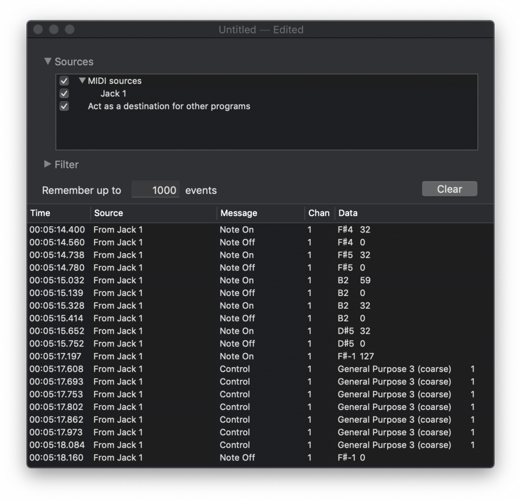
I tried using the Snoize MIDI Monitor for macOS. Well, for sure I could see events coming in, but for the life of me I couldn’t figure out how to see events going out, it just wasn’t working:
Time to get serious. Because I was doing this away from the office at night, I didn’t have the USB analyzer I normally use for day-to-day tasks with me. But I always have Wireshark installed to trace IP procols, and Wireshark can also capture and decode USB traffic.
You need to bring up the XHC20 interface on a Mac if you want to sniff it, which I did. With Wireshark set up and capturing, I started FL Studio and watched the messages pass through and set about figuring out what MIDI messages were sent.
The worst outcome would be a stream of undocumented SysEx messages. But even this is not such a big issue, with some ingenuity you can work things out. I’ll describe how later.
Anyway, capture in hand, time to dissect what’s going on.
Illuminating buttons
Opening up the capture, it’s clear that we will have some fun: there’s a bunch of SysEx messages going on, but the SysEx messages are interspersed with Control Change messages. Yes! Makes sense. Looking at the first set of control changes, most controls are set to zero and the conjecture is that a zero value turns off the LED. Each controller number corresponds to the MIDI note number on the input side, therefore its a 1:1 mapping between input and output for the controller. Not exactly MIDI complaint, but OK.
For instance, PLAY generates 90 33 7F when pressed. To illuminate it, send B0 33 xx where ‘xx’ is described below.
Next…send some control change events and see how the LEDs respond. I map each button and see how it responds to different values, it’s a fairly long process. Some buttons have only a single LED (red, yellow, green) and some have two LEDs (red-yellow, or green-yellow).
Here is a table of the controllers and what you can send to them:
| Red-only | Green-only | Yellow-only | Yellow-red | Yellow-green |
|---|---|---|---|---|
| PAT BACK | SOLO 1 | ALT | STEP | PATTERN |
| PAT NEXT | SOLO 2 | STOP | NOTE | PLAY |
| BROWSER | SOLO 3 | DRUM | ||
| GRID LEFT | SOLO 4 | PERFORM | ||
| GRID RIGHT | SHIFT | |||
| LOOP REC | ||||
| Control values | ||||
| 00 – Off | 00 – Off | 00 – Off | 00 – Off | 00 – Off |
| 01 – Dull Red | 01 – Dull Green | 01 – Dull Yellow | 01 – Dull Yellow | 01 – Dull Yellow |
| 02 – High Red | 02 – High Green | 02 – High Yellow | 02 – Dull Red | 02 – Dull Green |
| 03 – High Yellow | 03 – High Yellow | |||
| 04 – High Red | 04 – High Green | |||
Illuminating LEDs
There are also some rectangular LEDs between the solo buttons and the pad array. A simple programmatic scan with Control Change addressed to each controller uncovers them:
| Name | Control | xx Value |
|---|---|---|
| Rectangular LED 1 | B0 28 xx | 00 – Off |
| Rectangular LED 2 | B0 29 xx | 01 – Dull red |
| Rectangular LED 3 | B0 2A xx | 02 – Dull green |
| Rectangular LED 4 | B0 2B xx | 03 – High red |
| 04 – High green |
In addition to those, there’s a set of four circular red LEDs that indicate the control bank. Digging about, this is controlled by a single controller with mix of LED encodings rather than a controller per LED. Rather than explain, here’s a table:
| Message | Effect |
|---|---|
| B0 1B 00 | All LEDs off |
| B0 1B 01 | Channel LED on only |
| B0 1B 02 | Mixer LED on only |
| B0 1B 03 | User 1 LED on only |
| B0 1B 04 | User 2 LED on only |
| Then… | |
| B0 1B 10 (0001’0000) | All LEDs off |
| B0 1B 11 (0001’0001) | Channel LED on only |
| B0 1B 12 (0001’0010) | Mixer LED on only |
| B0 1B 13 (0001’0011) | Channel and Mixer LED on |
| B0 1B 14 (0001’0100) | User 1 LED on only |
| … | |
| B0 1B 1F (0001’1111) | All LEDs on |
Illuminating pads
This is where things get interesting. To recap, note on events do not illuminate pads. Nor does any control change, I tried all of them. The only thing left, for a standard MIDI implementation, is the get-out-of-jail System Exclusive message.
System Exclusive messages are a free-for-all of vendor entanglement. There are standardized SysEx messages, but as sure as one day follows the next, there is no commonality between controllers for this type of thing.
The Wireshark log contains a slew of SysEx messages that I have ignored until now. I’m thinking that one of them is going to be directed to the pads.
Here is something that I captured:
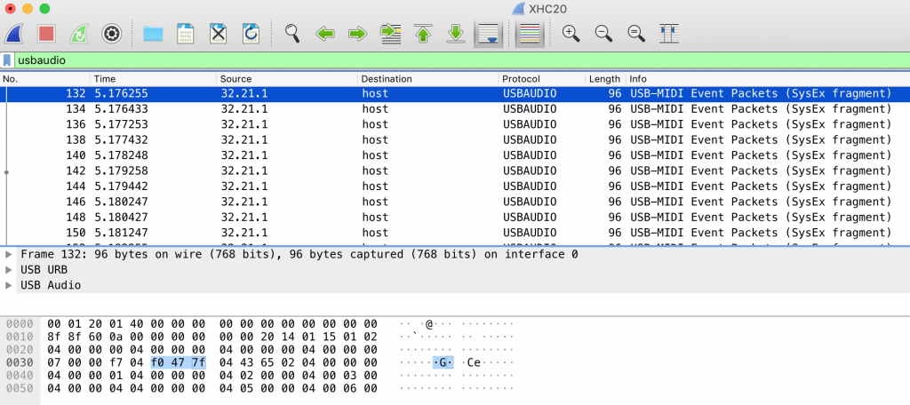
The highlighted bytes above show the start of my candidate SysEx message. For those of you familiar with MIDI but not with how it is transported across USB, this needs a bit of explanation and I refer you to the USB MIDI specification for the fine detail. For now, let’s just say that three bytes of MIDI SysEx content are transferred by four bytes of USB payload, the 04 before the F0 being an inserted prefix that indicates “MIDI SysEx message starts or continues.”
The curious case of the rogue 0F byte
Picking apart this message, this is what I find:
04 – “SysEx Continues” which is part of the USB encapsulation
F0 – System Exclusive
47 – Akai Manufacturer ID (see the MMA site for a list)
7F – The All-Call address
04 – “SysEx Continues,” and I will not show these bytes further
43 – Sub-ID byte #1 identifies “Fire” product
65 – Sub-ID byte #2 identifies the command
02 – First byte of SysEx payload
…
F7 – End of Exclusive
The USB specification says that all SysEx data uses that 04 leading byte, and the final packet containing the F7 End of Exclusive will be in a four-byte packet starting 05, 06, or 07.
Unfortunately, and this took me a long time to find, for macOS or FL Studio, I don’t know which, this is not true. Popping up in the middle of a SysEx stream is a rogue 0F byte:
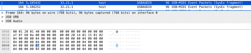
The 0F indicates, according to the USB MIDI specification, is “Single byte.” Well, yes, but it is not valid in a SysEx stream. And even Wireshark can’t correctly decode the SysEx message and asks me to submit a bug report!
Analyzing the SysEx
Working around this anomaly, what I find is a SysEx message whose payload is 258 bytes in length, and is always 258 bytes in length. The content of some bytes change, but many stay the same, and they increase by one every four bytes of payload:
02 00 00 xx xx xx 01 xx xx xx 02 xx xx xx 03 xx xx xx 04 xx xx xx … 3F xx xx xx
So, I have identified a pattern here. Can you see what I see? Let’s make is clearer:
02 00
00 xx xx xx
01 xx xx xx
02 xx xx xx
03 xx xx xx
04 xx xx xx
...
3F xx xx xx
There are 4×16 = 64 pads, counting 00 through 3F hex. Those increasing bytes in the SysEx above look like pad indexes to me. And the three following bytes? My guess is that the are good to contain red, green, and blue values. And the 02 00 at the head? Well, that my dear reader, is a length that indicates how many following bytes there are in the SysEx message: 64 pads x (1 pad index + 3 color levels) = 64 x 4 = 256 bytes.
What’s up with the length?
For those of you with embedded knowledge but no MIDI knowledge, you’ll think I’ve made a mistake: 0200 hex represents 512 not 256. So this needs some explanation.
MIDI data bytes have ranges 00 through 7F because status bytes are 80 through FF. You can’t plain encode a 16-bit length in a MIDI data stream because (for instance) a length of 511 would translate to 01 FF. That FF is a Reset command, and that means your device is indeed reset. Instead you must encode any data in units of seven bits.
A specific length is encoded in two bytes, the first being bits 7 through 13 and the second being bits 0 through 6. Encoding 256 using this scheme (which is 64×4), results in 02 00. Bingo!
Changing individual pads
It seems that FL Studio sends the entire pad array in a single SysEx message, which is probably a good thing as then all pads change color in unison. But it doesn’t need to.
To construct a SysEx message that changes the pad colors:
F0 – System Exclusive
47 – Akai Manufacturer ID (see the MMA site for a list)
7F – The All-Call address
43 – Fire Sub-ID
65 – Write Pad Array command
hh – High length byte, bits 7 through 13 of following payload
ll – Low length byte, bits 0 through 7 of following payload
Repeat for pads you want to change {…
ii – Pad index, 00 top left through 3F bottom right
rr – Red level, 00 through 7F
gg – Green level, 00 through 7F
bb – Blue level, 00 through 7F
…}
F7 – End of Exclusive
Simple as that! To make it super-real, we can change pad 4 of row 2 to full-intensity blue by sending the following SysEx message:
F0 47 7F 43 65 00 04 23 00 00 7F F7
In C code, writing a single pad looks like this:
void FIRE_SetPadColor(USBH_MIDI_HANDLE hMIDI,
                      unsigned         R,
                      unsigned         C,
                      U32              Color) {
  FIRE_SYSEX_Begin();
  FIRE_SYSEX_Add(hMIDI, 0x47);                  // AKAI
  FIRE_SYSEX_Add(hMIDI, 0x7F);                  // All-Call
  FIRE_SYSEX_Add(hMIDI, 0x43);                  // Fire
  FIRE_SYSEX_Add(hMIDI, 0x65);                  // WRITE PADS
  FIRE_SYSEX_Add(hMIDI, 0);                     // Message length: 4 bytes
  FIRE_SYSEX_Add(hMIDI, 4);
  FIRE_SYSEX_Add(hMIDI, R*0x10 + C);            // Pad index
  FIRE_SYSEX_Add(hMIDI, (Color >> 17) & 0x7F);  // Red
  FIRE_SYSEX_Add(hMIDI, (Color >>  9) & 0x7F);  // Green
  FIRE_SYSEX_Add(hMIDI, (Color >>  1) & 0x7F);  // Blue
  FIRE_SYSEX_End(hMIDI);
}
Extending this to a pad array is left as an exercise. And yes, I have done it myself.
Some additional controls
Controller 127 responds to changes. Sending the value 0 to it turns all LEDs off. Sending turns all LEDs on, so dual-LED buttons have both LEDs turned on simultaneously and all pads are white. Useful? No idea.
And so it continues
With the input side and buttons and pads conquered, time to tackle the OLED. Read about it in part 3!